
Installation of the Frogulator is of moderate difficulty, with the need to fully clean multiple through holes on the existing DC regulator. Reading this guide in preparation is highly recommended for success!
Tools Needed
- Soldering iron
- Solder
- Solder sucker
- Flux(optional)
- Solder wick(optional)
- Plastic spudger(optional)
- Flush cutters(optional)
Step 1 - Remove the stock DC regulator
The Frogulator is designed to replace the original DC regulator, so the original must be removed in preparation.

On the back side of the GBC/GBP motherboard, you will see the either 7(GBC) or 6(GBP) pins of the DC regulator in the indicated area. Use a soldering iron to heat each pin individually, and a solder sucker to remove the solder and free the pin. Solder wick can optionally be used to help remove stubborn solder from the through holes.

Step 2 - Prepare button test pads
With the solder removed from the through holes and pins -- you may need to gently push perpendicular to each pin with a plastic spudger to break them free of their respective through holes(don't force it, opt for wick if necessary) -- gently pry on the regulator to remove it from the board.

Once removed, make sure that all through holes are fully cleared of old solder. If a hole is partially blocked, reheat it with your iron and clear the blockage with either a solder sucker or solder wick.

Step 3 - Place header pins and Frogulator
Your Frogulator kit should come with two header pin sections of 3 pins each. Place one section into each column of holes on the motherboard in the top most position -- pin 4 on the GBC motherboard should be empty. The pressure of the header pins on the through holes should hold the assembly securely in place temporarily.

Step 4 - Solder header pins to Frogulator
From the front of the GBC motherboard with the Frog facing up, solder the header pins to their respective pads on the Frogulator. It's highly recommended that you bring the soldering iron in from the outside edge of each column of pins to avoid getting solder on the large exposed gold area around the Frog image.
Refer to the below images for the proper angle of attack.


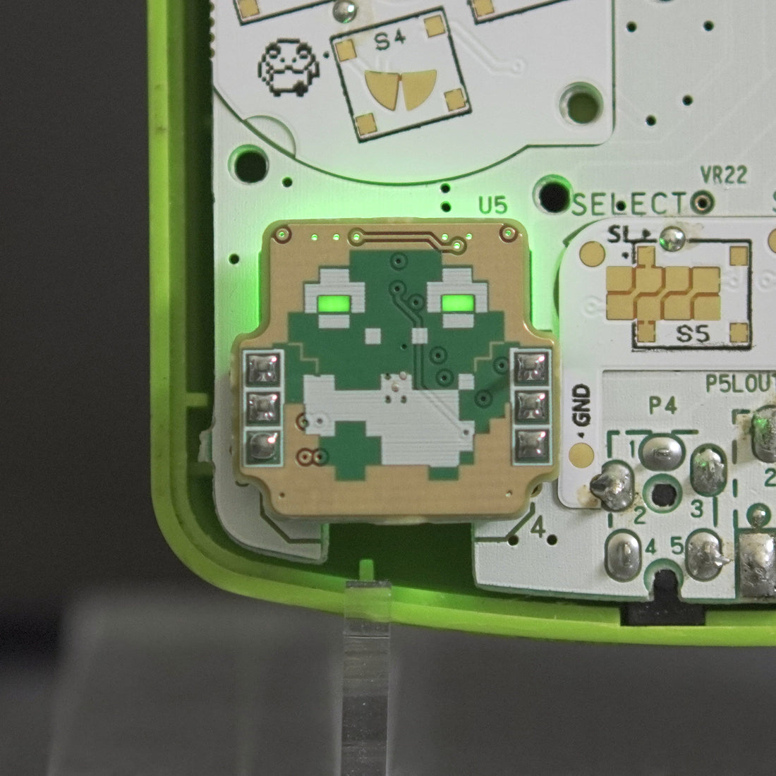
The Frogulator should look like the below image once all 6 pins have been soldered.

Step 5 - Solder header pins to GBC
With the Frogulator firmly attached to the header pins, flip over the GBC board to expose the header pins poking through the other side.

With your soldering iron, solder each header pin to the corresponding pad on the GBC, making sure the solder fully floods the through hole to make a strong connection.

At this stage, you can optionally use flush cutters to trim the pins to more closely match the length of the original DC regulator, but this is not necessary.
Step 6 - Setting voltage threshold
The Frogulator -- like the battery indicator mod -- has two user selectable voltage thresholds for when the bad battery LEDs turns on, one to support traditional AA batteries, and another to support single cell LiPo batteries.
The following image highlights the switch used to select which mode to use. The top position is for LiPo batteries, while the bottom position(marked by a white bar) is for AA batteries.

That's it, you just got frogged!
Troubleshooting
The eyes never turn red when using a LiPo battery
Double check that the Frogulator is in LiPo mode, per the directions in step 6. Running the Frogulator in AA mode while using a LiPo will result in the eyes always lighting up green. Alternatively, you may be using a LiPo kit that's doing something unexpected and isn't compatible with this mod. Check out my discord for further troubleshooting help!
The Game Boy doesn't turn on after installing the Frogulator
This could come down to a few issues:
- An error during installation caused a short, either on the GBC or the Frogulator. Verify that the pins of the Frogulator are all soldered separately, with no bridging on either the connections to the motherboard, or to the Frogulator. Ensure that the pins on the Frogulator have not accidentally been soldered to the large gold area around the Frogulator. A multimeter can be very helpful tracking down shorts.
- One or more pins is not fully soldered on either the GBC or the Frogulator. Double check all connections, and reapply heat or solder if necessary.
For further troubleshooting, please hop into my discord and ask there!