
Installation of the Game Boy Color tactile switch mod is fairly straightforward, but requires a bit of finesse. I highly recommend reading this guide before attempting to install it yourself!
Tools Needed
- Soldering iron
- Solder
- Flush cutters OR scissors
- Flux(optional, recommended only for experienced folks)
- Kapton tape(optional, to protect original button contacts)
Step 1 - Separate tactile switch boards
Your tactile switch boards will likely come as a single PCB panel. Simply cut at the dotted margins with a pair of flush cutters or scissors to separate them and remove the small tabs.
Step 2 - Prepare button test pads
Before installing the tactile switch boards, it's highly recommended that you prepare the button test pads on the GBC motherboard by pre-tinning them, as shown below. The test pads are labeled P00, P01, P02, P03, P10, P11, P12, and P13.

Tip: During this process, it's possible you might accidentally get solder on the original button contacts. To avoid this -- and maintain the option of removing the tactile mod in the future -- I recommend covering the contacts in kapton tape during the test pad tinning.
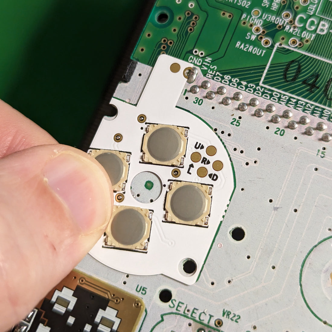
Step 3 - Install D-pad board
To install the D-pad board, carefully place it over the original D-pad area, making sure that the 4 vias near the buttons line up with the pre-tinned test pads from earlier, as well as the GND pin on the cartridge reader.

With your soldering iron, carefully tack the board into place on all four vias and the ground pin, making sure all are securely connected. If necessary, add additional solder to each via after tacking in place for a strong connection. Press your tweezer tips on opposite sides of each via while heating them to make sure the board is flat against the motherboard.

Step 4 - Install A/B board
Similar to the D-pad, place the A/B board on top of the A/B button area, lining up the two pre-tinned test pads from earlier inside the corresponding vias on the board. The gold strip at the bottom should align closely with the negative battery terminal.

Again, carefully tack the board into place between the vias and test pads. Additionally, with your iron touching both the gold strip at the bottom and the negative battery terminal, apply solder until the two parts bridge together. This provides a good mechanical connection, as well as a potential ground connection.

At this point for the simplest install, apply solder to and bridge the highlighted GND_ALT pads to establish a ground connection for the buttons through the negative battery terminal. Note that this will cause the A and B buttons to not work while the GBC is plugged into a DC power jack. If this is important to you, leave GND_ALT alone, and instead run a wire(not pictured) from the GND pad on the left to any suitable GND on the motherboard.

Step 5 - Install start/select board
Just like in the previous steps, align the start/select board over the original start/select buttons, aligning the the two vias with the previously tinned test points on the motherboard, as well as pin 2 on the DC jack.

Very carefully tack the board into place using your soldering iron, connecting the vias to the test points, as well as pin 2 on the DC jack to GND on the button board. Be very careful with the SL via, as it sits partially underneath the tactile switch for select.

Step 6 - Clean up(OPTIONAL)
Optionally, if you want cleaner solder joints on each of the boards, very carefully apply a small amount of tacky flux to each joint and reheat using your solder iron.
For an even cleaner appearance, very carefully clean any flux residue using a q-tip dipped in isopropyl alcohol.
You must be VERY careful doing either of these steps, as it's relatively easy for both of these materials to soak into the tactile switches and make them less responsive. Most solder points will be hidden behind either the membranes or other parts of the system, so aesthetic gains from cleaning are minimal.
Step 7 - Reassemble GBC as normal
Reassemble the GBC as you normally would, making sure to include the membranes, as the buttons will not reach the switches without them.
That's it, you're done! Enjoy the click.
Troubleshooting
The A and B buttons don't work
This is likely because you didn't do one(and only one) of the following:
- Bridge the two GND_ALT pads on the A/B board to establish a ground connection through the battery terminal, or
- Run a wire from the GND on the A/B board to a suitable ground on the board
One or more buttons are unresponsive
If you get sporadic inputs from one or more buttons, it could be on of the following:
- Flux or isopropyl alcohol made its way into the problem switches during cleaning. This can be cleaned, but requires peeling back the metal dome on the problem switch and cleaning out the contaminant.
- The via corresponding to the problem button has a weak connection to the underlying test point. Reflow the solder on the via, apply downward pressure on either side using a pair of tweezers to ensure proper flatness against the GBC motherboard.
My board is missing one or more test points because of corrosion
If you're using a badly corroded board where one or more test points are missing, you will need to run wires for the affected buttons. See this video for instructions on where to wire.
Check out my discord for further troubleshooting help!